
Imagine receiving an LED street lamp advertised as a 120W model, only to see a different number on a power meter. Does that automatically mean the specification is wrong?
Before reaching a conclusion, establish what the stated wattage represents, which operating mode is active, and whether the instrument is measuring the correct electrical quantity. A useful verification process should answer a precise question: How much real electrical power does the complete luminaire consume under the specified operating conditions?
This guide focuses on mains-powered LED street lamps and provides a practical approach to sample evaluation and purchase acceptance. For the example specification used below, the required power factor is greater than 0.95.
1. Clarify What the Rated Wattage Represents
Begin with the product specification rather than the number printed on an internal component. Ask the supplier to distinguish between the complete luminaire’s input power, the power delivered to the LED module, and the driver’s maximum output capacity. These figures are not interchangeable, and the driver’s rated capacity should not be treated as a measurement of the assemb LED street lamp’s consumption.
For purchase verification, specify that the measurement should cover the complete luminaire at its AC input, including driver losses and any accessories included in the agreed configuration.
In a separate, simplified illustration, a driver delivering 108W to an LED module at 90% conversion efficiency would require:
Input power = LED output power ÷ Driver efficiency
Input power = 108W ÷ 0.90 = 120W
This example explains the distinction between input and output power. The 90% figure represents conversion efficiency, not power factor. Conversion efficiency compares output power with input power; power factor compares real input power with apparent input power.
Before testing, ask the supplier to confirm exactly which power value appears on the product label and specification sheet.
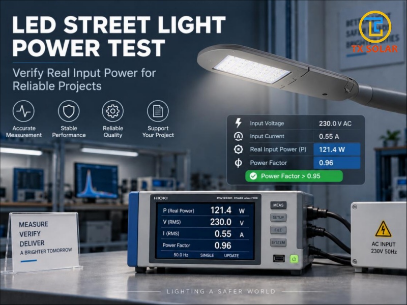
2. Use a Meter That Measures Real Power
Select a power analyzer or wattmeter with a suitable measurement range and documented accuracy. Confirm that it measures active power in watts, rather than displaying only voltage, current or apparent power. An appropriate power analyzer measures voltage and current together to determine real power.
A true-RMS multimeter can measure AC voltage or current, including distorted waveforms within its specified capabilities. However, “true-RMS” does not automatically mean that the instrument measures active power. A meter displaying only volts and amperes is not a complete substitute for a wattmeter.
For the inspection record, request the instrument model, identification number and calibration status alongside the measured results.
Have a qualified electrical technician perform mains testing using correctly rated equipment and enclosed connections. Maintain protective earthing where required, disconnect the supply before changing connections, and do not open or probe an energized luminaire.
3. Distinguish Real Power from Apparent Power
For a single-phase AC supply, multiplying RMS voltage by RMS current gives apparent power, expressed in volt-amperes:
Apparent power (VA) = RMS voltage × RMS current
Real input power also accounts for power factor:
Real input power (W) = RMS voltage × RMS current × Power factor
Use true power factor, which accounts for the relationship between real and apparent power, rather than assuming that a phase-angle measurement alone is sufficient for a potentially distorted waveform.
For this example specification, the requirement is Power Factor > 0.95. The following illustrative calculation uses PF = 0.96.
|
Parameter |
Illustrative Value |
|
Declared luminaire input power |
120W |
|
Input voltage |
230.0V AC |
|
Input current |
0.55A RMS |
|
Required power factor |
> 0.95 |
|
Example power factor |
0.96 |
|
Calculated apparent power |
126.5VA |
|
Calculated real input power |
121.44W |
The calculation is:
Apparent power = 230.0 × 0.55 = 126.5VA
Real input power = 230.0 × 0.55 × 0.96 = 121.44W
In this example, the luminaire consumes approximately 121.4W, not 126.5W. Reporting 126.5W would incorrectly treat apparent power as real power.
These values are illustrative, not actual product test results. For a real inspection, record the analyzer’s direct watt reading instead of reconstructing it from rounded voltage, current and power-factor displays.
4. Confirm the Supply and Control Settings
Document the test voltage, frequency and operating environment. Use the conditions stated in the product specification or agreed test method. ANSI/IES LM-79-24 addresses electrical supply conditions, environmental conditions and instrument calibration for solid-state lighting measurements.
Next, confirm the driver configuration. LED drivers may provide adjustable output settings and dimming functions, so the selected operating condition matters when interpreting a power measurement.
For a full-output acceptance test, request the manufacturer’s specified full-output configuration. Record the programmed current and control command, and confirm that a scheduled dimming profile or sensor command is not reducing output.
Also identify the input voltage and operating condition to which the PF > 0.95 requirement applies. Record those conditions with the result rather than treating one reading as evidence for every possible operating mode.
Do not increase the driver beyond its approved configuration simply to make the meter match the advertised number. The purpose is to verify the supplied product, not alter it until a preferred reading appears.
5. Wait for Stable Operation
Do not use the first reading after switch-on as the final result. Allow the luminaire to stabilize according to the selected test procedure, in its specified operating orientation and with appropriate ventilation. Stabilization, orientation and thermal conditions are addressed in ANSI/IES LM-79-24.
For the inspection record, log readings over time and retain the stabilized value. Avoid imposing an arbitrary warm-up period on every product without checking the applicable procedure.
If the reading continues to drift, record the behavior and investigate before issuing an acceptance decision. Request the operating duration and environmental conditions together with the final wattage.
A photograph of a single meter reading can document what the instrument displayed at that moment, but it cannot establish that the luminaire had reached stable operation.
6. Compare the Result with the Agreed Specification
After obtaining a valid measurement, calculate the difference from the declared input power:
Power deviation (%) = [(Measured power − Declared power) ÷ Declared power] × 100
For the illustrative 120W luminaire with a calculated input power of 121.44W:
Power deviation = [(121.44 − 120) ÷ 120] × 100
Power deviation = +1.2%
The input power in this example is therefore 1.2% above the declared value. This does not automatically establish whether the product passes or fails.
Use the applicable requirements and agreed acceptance tolerance, considering measurement uncertainty where relevant. ANSI/IES LM-79-24 addresses measurement uncertainty and distinguishes tolerance intervals from acceptance intervals.
Evaluate the power-factor requirement separately. The illustrative value of 0.96 is greater than 0.95, but an actual acceptance decision should use the recorded measurement, specified test conditions and agreed decision rule.
A wattage close to the declared value does not, by itself, demonstrate compliance with the power-factor requirement. Likewise, meeting the power-factor requirement does not prove that input power is within the agreed tolerance.
Before ordering, ask whether the stated wattage is a nominal operating value, a maximum consumption limit or an adjustable setting. Agree on the acceptance criteria before testing.
7. Match the Test Record to the Delivered Product
Request a record identifying the sample, driver model, output setting, supply conditions, stabilized input power, power factor and measurement equipment. Keep the sample serial number or batch reference with the report.
Where independent verification is required, request a laboratory report using the agreed measurement method. ANSI/IES LM-79-24 covers electrical and optical measurements and includes reporting requirements; a routine meter check should not be presented as a complete LM-79 test.
Check that the report corresponds to the ordered configuration, not merely another luminaire with a similar housing. For bulk purchasing, agree on a sampling plan covering the relevant models and driver settings. One satisfactory sample provides evidence for that sample, not automatically for every unit in the shipment.
Finally, keep power verification separate from overall lighting acceptance. An electrical watt reading does not establish luminous flux or light distribution; those are separate measured quantities.
Ask for the electrical test record and the relevant photometric documentation as complementary evidence rather than treating either one as a substitute for the other.
Conclusion
Verifying LED street lamp power is more than checking whether a display matches a label. The measurement needs a defined scope, an appropriate instrument, confirmed settings, stable operation and clear acceptance criteria.
For a specification requiring Power Factor > 0.95, verify that requirement alongside the actual input wattage under the agreed test conditions. Keep both results linked to the tested luminaire and its approved configuration.
For your next LED street lighting order, discuss the declared input power, power-factor requirement, control settings and required test documentation with Tianxiang before approving the sample. A traceable measurement is more useful than an isolated wattage claim.
Post time: Sep-23-2026


